Изображения являются только для ссылки
BF998R
+БОМRF MOSFET Transistors N-channel dual-gate MOSFET
-
ПроизводительКомпания NXP Semiconductors
-
Мфр. Часть #BF998R
-
В наличии7322
365 Дни гарантии качества
7*24 часы обслуживания каранти
90-гарантия послепродажного дня
Гарантия подлинного продукта
Спецификации
| Атрибут | Ценность |
Обзор
Description
The BF998R is a type of N-channel dual-gate MOSFET (Metal-Oxide-Semiconductor Field-Effect Transistor) commonly used in high-frequency applications, such as RF mixers, amplifiers, and oscillators. It is particularly valued for its low noise figure and high input impedance, making it suitable for use in sensitive RF front-end circuits. The dual-gate design allows for better control over gain and frequency response, as one gate can be used for signal input while the other is used for gain control or feedback purposes.
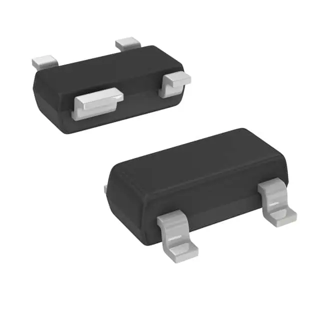
Key characteristics of the BF998R include its low noise performance, making it ideal for applications where signal integrity is crucial, and its ability to operate at high frequencies, often in the VHF and UHF range. It typically comes in a small SOT-143 package, which is beneficial for compact circuit designs. This component is favored in applications demanding precision and stability in signal processing, such as in communication devices and broadcasting equipment.
Key characteristics of the BF998R include its low noise performance, making it ideal for applications where signal integrity is crucial, and its ability to operate at high frequencies, often in the VHF and UHF range. It typically comes in a small SOT-143 package, which is beneficial for compact circuit designs. This component is favored in applications demanding precision and stability in signal processing, such as in communication devices and broadcasting equipment.
Equivalent
The BF998R is a dual-gate MOSFET commonly used in RF applications. Equivalent products include:
1. BF998 - Similar performance with different packaging.
2. BF998WR - A version with a wider range.
3. BF981 - Another dual-gate MOSFET with comparable characteristics.
These alternatives should be checked for specific parameter variances such as gain, noise figure, and frequency range to ensure they meet your application's requirements. Always refer to the manufacturer's datasheets for precise compatibility.
1. BF998 - Similar performance with different packaging.
2. BF998WR - A version with a wider range.
3. BF981 - Another dual-gate MOSFET with comparable characteristics.
These alternatives should be checked for specific parameter variances such as gain, noise figure, and frequency range to ensure they meet your application's requirements. Always refer to the manufacturer's datasheets for precise compatibility.
Features
The BF998R is a dual-gate MOSFET transistor, commonly used in RF applications due to its high performance and reliability. Key features include:
1. Dual-Gate MOSFET Design: The dual-gate configuration allows for better control over gain and noise figure, making it ideal for RF amplification and mixers.
2. High Frequency Capability: It operates effectively at very high frequencies, suitable for applications in the VHF and UHF bands.
3. Low Noise Figure: The BF998R is designed to provide a low noise figure, which is critical for improving the sensitivity of RF receivers.
4. High Gain: It offers substantial gain, enhancing the signal strength in various applications.
5. Low Power Consumption: The BF998R is efficient in power usage, making it suitable for battery-operated devices.
6. Surface-Mount Package: Typically available in a small SOT-143 package, which supports compact circuit designs.
These features make the BF998R a versatile choice for designers working on RF amplifier and mixer circuits in telecommunications and broadcasting equipment.
1. Dual-Gate MOSFET Design: The dual-gate configuration allows for better control over gain and noise figure, making it ideal for RF amplification and mixers.
2. High Frequency Capability: It operates effectively at very high frequencies, suitable for applications in the VHF and UHF bands.
3. Low Noise Figure: The BF998R is designed to provide a low noise figure, which is critical for improving the sensitivity of RF receivers.
4. High Gain: It offers substantial gain, enhancing the signal strength in various applications.
5. Low Power Consumption: The BF998R is efficient in power usage, making it suitable for battery-operated devices.
6. Surface-Mount Package: Typically available in a small SOT-143 package, which supports compact circuit designs.
These features make the BF998R a versatile choice for designers working on RF amplifier and mixer circuits in telecommunications and broadcasting equipment.
Pinout
The BF998R is an RF N-channel dual gate MOSFET commonly used in RF amplification and mixer applications. It typically comes in an SOT-143 package with a 4-pin configuration. The pin functions are as follows:
1. Pin 1 (S): Source
2. Pin 2 (G1): Gate 1 (Control Gate)
3. Pin 3 (G2): Gate 2 (Gain Adjustment Gate)
4. Pin 4 (D): Drain
The dual-gate configuration allows for better control over the gain and improved signal handling capabilities, making it suitable for RF front-end applications.
1. Pin 1 (S): Source
2. Pin 2 (G1): Gate 1 (Control Gate)
3. Pin 3 (G2): Gate 2 (Gain Adjustment Gate)
4. Pin 4 (D): Drain
The dual-gate configuration allows for better control over the gain and improved signal handling capabilities, making it suitable for RF front-end applications.
Manufacturer
The BF998R is manufactured by Infineon Technologies AG. Infineon is a German semiconductor manufacturer that specializes in electronic components and systems. The company focuses on various sectors, including automotive, industrial power control, power management, digital security solutions, and IoT applications. Infineon's products are essential for enabling efficient energy management, connectivity, and security in a wide range of electronic devices and systems.
Application
The BF998R is a dual-gate MOSFET designed primarily for RF applications. Key application areas include RF amplification, mixing, and switching in telecommunications, satellite systems, and broadcasting equipment. It is commonly used in front-end receiver circuits and RF signal processing due to its low noise figure and high gain characteristics. The dual-gate design allows for improved control of gain and bandwidth, making it suitable for tuning and frequency modulation. Additionally, it is utilized in oscillator circuits and as a variable gain amplifier in RF and microwave frequency ranges. Its versatility makes it valuable in various RF and microwave electronic devices.
Package
The BF998R is a dual-gate MOSFET commonly used in RF applications. It typically comes in a SOT-143 package, which is a small, surface-mount package suitable for high-frequency and low-noise applications.