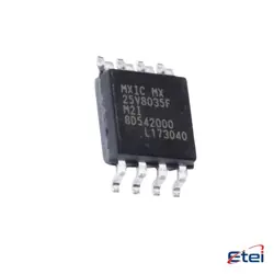
Изображения являются только для ссылки
IPA65R400CE
+БОМ-
Производителькомпанией Infineon Technologies
-
Мфр. Часть #IPA65R400CE
-
В наличии4527
365 Дни гарантии качества
7*24 часы обслуживания каранти
90-гарантия послепродажного дня
Гарантия подлинного продукта
Спецификации
| Атрибут | Ценность |
| Technology | Si |
| Packaging | Tube |
| Brand | Infineon Technologies |
| Product Type | MOSFETs |
| Subcategory | Transistors |
| Mounting Type | Through Hole |
| Height | 16.15 mm |
| Length | 10.65 mm |
| Width | 4.85 mm |
| Unit Weight | 0.068784 oz |
| Package / Case | TO-220FP-3 |
| Vds - Drain - Source Breakdown Voltage | 650 V |
Обзор
Description
The IPA65R400CE is a high-performance N-channel MOSFET designed for applications requiring efficient power management. It features a maximum drain-source voltage (V_DS) of 650V and a continuous drain current (I_D) of 400A, making it suitable for high-voltage and high-current applications. The device is optimized for low on-resistance (R_DS(on)), which minimizes power loss during operation and enhances overall efficiency.
Key features include a fast switching speed, low gate charge, and robust thermal performance, allowing it to operate effectively in demanding environments, such as power converters, inverters, and motor drives. The IPA65R400CE is housed in a TO-247 package, facilitating effective heat dissipation and easy integration into various circuit designs.
Overall, the IPA65R400CE is an ideal choice for engineers seeking reliable and efficient solutions in power electronics, particularly in renewable energy systems, electric vehicles, and industrial applications.
Key features include a fast switching speed, low gate charge, and robust thermal performance, allowing it to operate effectively in demanding environments, such as power converters, inverters, and motor drives. The IPA65R400CE is housed in a TO-247 package, facilitating effective heat dissipation and easy integration into various circuit designs.
Overall, the IPA65R400CE is an ideal choice for engineers seeking reliable and efficient solutions in power electronics, particularly in renewable energy systems, electric vehicles, and industrial applications.
Equivalent
The IPA65R400CE is an N-channel MOSFET from Infineon with a 400V rating. Equivalent products include the STP40NF400 from STMicroelectronics, the FGA40N40 from ON Semiconductor, and the IRF840 from Texas Instruments. Ensure to check specifications like V_DS, R_DS(on), and gate threshold voltages to confirm compatibility for specific applications.
Features
The IPA65R400CE is an N-channel MOSFET designed for high-performance applications. Key features include:
1. Voltage Rating: It has a maximum drain-source voltage of 650V, making it suitable for high-voltage applications.
2. Current Handling: The device can handle continuous drain currents up to 400A, allowing for robust power management.
3. Low On-Resistance: With an RDS(on) of around 0.065 ohms, it ensures efficient conductivity and reduced power loss.
4. High-Speed Switching: It supports fast switching capabilities, making it ideal for applications like power supplies and motor drives.
5. Thermal Performance: The MOSFET is designed to operate efficiently at high temperatures, with a low thermal resistance.
6. TO-247 Package: It comes in a TO-247 package, facilitating easy heatsinking and improved thermal management.
These features make the IPA65R400CE suitable for a variety of applications, including renewable energy systems, industrial motor drives, and power converters.
1. Voltage Rating: It has a maximum drain-source voltage of 650V, making it suitable for high-voltage applications.
2. Current Handling: The device can handle continuous drain currents up to 400A, allowing for robust power management.
3. Low On-Resistance: With an RDS(on) of around 0.065 ohms, it ensures efficient conductivity and reduced power loss.
4. High-Speed Switching: It supports fast switching capabilities, making it ideal for applications like power supplies and motor drives.
5. Thermal Performance: The MOSFET is designed to operate efficiently at high temperatures, with a low thermal resistance.
6. TO-247 Package: It comes in a TO-247 package, facilitating easy heatsinking and improved thermal management.
These features make the IPA65R400CE suitable for a variety of applications, including renewable energy systems, industrial motor drives, and power converters.
Pinout
The IPA65R400CE is an N-channel MOSFET manufactured by Infineon, featuring a total of 5 pins. The pin configuration and their functions are as follows:
1. Gate (G): This pin is used to control the MOSFET. A voltage applied here turns the device on or off.
2. Drain (D): This is the main current-carrying terminal where the load is connected. Current flows from the drain to the source when the MOSFET is on.
3. Source (S): This terminal is connected to the ground or negative supply in a typical application. Current flows from this pin to the drain when the MOSFET is conducting.
4. Gate-Source (GS): Not a separate pin but indicates the voltage between the gate and source, crucial for controlling the MOSFET operation.
5. Drain-Source (DS): Also not a separate pin, refers to the voltage between these two terminals when the MOSFET is in operation.
This MOSFET is designed for high efficiency and low switching losses, suitable for applications like power supplies and motor control.
1. Gate (G): This pin is used to control the MOSFET. A voltage applied here turns the device on or off.
2. Drain (D): This is the main current-carrying terminal where the load is connected. Current flows from the drain to the source when the MOSFET is on.
3. Source (S): This terminal is connected to the ground or negative supply in a typical application. Current flows from this pin to the drain when the MOSFET is conducting.
4. Gate-Source (GS): Not a separate pin but indicates the voltage between the gate and source, crucial for controlling the MOSFET operation.
5. Drain-Source (DS): Also not a separate pin, refers to the voltage between these two terminals when the MOSFET is in operation.
This MOSFET is designed for high efficiency and low switching losses, suitable for applications like power supplies and motor control.
Manufacturer
The IPA65R400CE is manufactured by Infineon Technologies, a German semiconductor manufacturer. Infineon specializes in a wide range of semiconductor solutions, including power semiconductors, microcontrollers, and sensors. The company focuses on various industries such as automotive, industrial power control, and IoT (Internet of Things) applications. Infineon is known for its innovation in power efficiency and safety technologies, contributing to advancements in energy-saving solutions and smart technologies across multiple sectors. Founded in 1999, Infineon has established itself as a key player in the global semiconductor market, offering products that cater to the demands of modern electronics and providing solutions that enhance performance and sustainability.
Application
The IPA65R400CE is a high-performance power MOSFET, primarily used in various applications such as:
1. Switching Power Supplies: For efficient power conversion and regulation.
2. DC-DC Converters: In applications requiring voltage step-down or step-up.
3. Motor Drives: In electric vehicles and industrial automation for efficient motor control.
4. Class D Amplifiers: In audio applications for efficient signal amplification.
5. LED Drivers: For powering LED lighting systems with high efficiency.
6. Renewable Energy Systems: In solar inverters and energy storage solutions.
Its high voltage and current capabilities make it suitable for demanding applications.
1. Switching Power Supplies: For efficient power conversion and regulation.
2. DC-DC Converters: In applications requiring voltage step-down or step-up.
3. Motor Drives: In electric vehicles and industrial automation for efficient motor control.
4. Class D Amplifiers: In audio applications for efficient signal amplification.
5. LED Drivers: For powering LED lighting systems with high efficiency.
6. Renewable Energy Systems: In solar inverters and energy storage solutions.
Its high voltage and current capabilities make it suitable for demanding applications.
Package
The IPA65R400CE is packaged in a TO-247 format. This package type is designed for high-power applications, offering good thermal performance and ease of mounting.